
EasyDraw Edit Tool
Adjusting Lines and Arcs
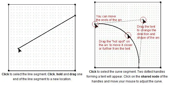
The Edit tool allows you to to make simple adjustments to lines and arcs.
Adding Nodes
The Edit tool also allows you to add nodes to an existing segment. Once you have added nodes, you can join other lines or arcs to them.
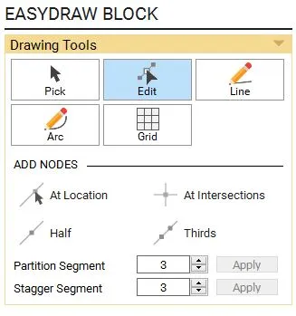
Add node At Location
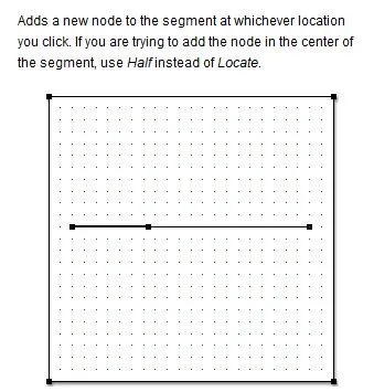
Click to select a segment. Click At Location in the palette. Click on the segment to add a node. This will split the segment into two segments at that point.
Add node At Intersections
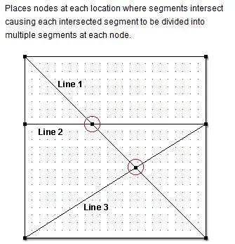
Click to select a segment. Click At Intersections in the palette. Notice the new nodes added at the intersections. Also, the initial three lines now get split into multiple segments at each new node.
Add node at Half
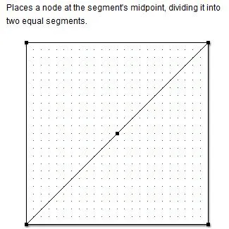
Click to select a segment. Click Half in the palette to divide the segment evenly into 2 segments.
Add nodes at Thirds
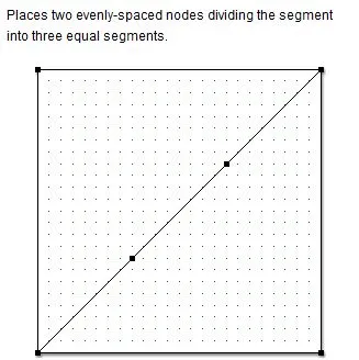
Click to select a segment. Click Thirds in the palette to divide the segment into three equal segments.
Partition Segment
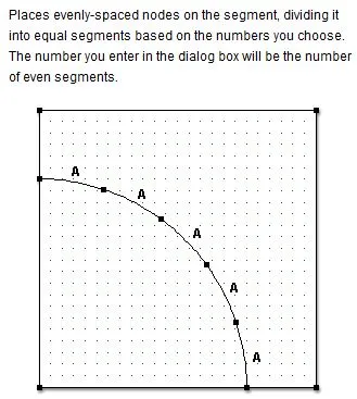
Click to select the segment. In the palette, click the up and down arrows next to Partition Segment for the number of equal segments that will partition the arc. Click Apply. For the example above, the number 5 was entered into the dialog box. Each segment marked A indicates equal lengths.
Stagger Segment
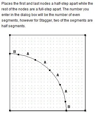
Click to select the segment. In the palette, click the up and down arrows next to Stagger Segment to change the numbers. Click Apply. For the example above, the number 5 was entered for Stagger Segment. When you click Apply, the segment is split into 4 equal segments (A) and 2 segments half the length of the other segments (B)—resulting in 5 equal segments.
PolyDraw Edit Tool
The Edit tool allows you to edit and change the shape of patches by moving nodes to reshape the patch, as well as adding nodes to line segments.
To Change the Shape of the Patch
- Position the mouse over a node.
- Click on the node with your left mouse button, hold, and drag it to a new location.
Note:
- The PolyDraw layer of the PolyDraw worktable is permanently set to Snap to Grid. When you are moving nodes on the worktable, you will notice the node snapping to the closest grid point.
- Be sure that your patches don’t overlap one another. You may find it just as easy to redraw a block than to edit an existing block.
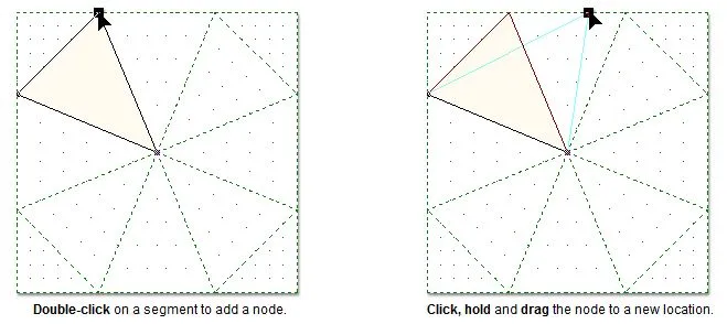
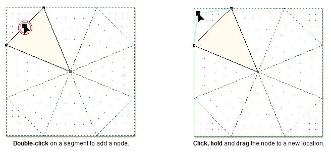
To Add and Delete Nodes
- Position the mouse over a line segment.
- Double-click with the left mouse button to add a node.
- Click on the new node with your left mouse button, hold, and drag it to a new location.
To delete a newly added node, double-click the node again.
Note:
The PolyDraw layer of the PolyDraw worktable is permanently set to Snap to Grid. When you are moving nodes on the worktable, you will notice the node snapping to the closest grid point.
Applique Edit Tool
The Edit tool allows you to edit and change the shape of objects by using nodes and their handles to edit the curves and angles.
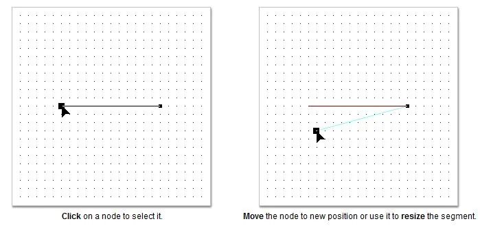
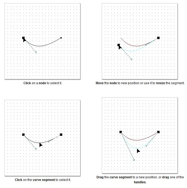
To Change a Line Segment
- Position the mouse over either end node.
- Press the left mouse button to pick up the node and move it to a new location
To Change a Curve Segment
- Position the mouse over either end node or the curve segment.
- Press the left mouse button to pick up the node or curve and drag it until it’s the shape you want.
Editing Patches with the Shape Tool
You must have at least one segment selected for the commands to be available. The pictures below show the result of applying each of the commands.
Add Node/Delete Node
![]()
![]()
You can also double-click on the segment to add a node, and double-click on a node to delete it.
Join Segments
![]()
Joins two selected nodes to create one segment or curve.
Break at Node
![]()
Breaks the segment at the selected node.
Convert to Line
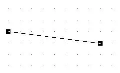
Converts a curve to a straight line segment.
Convert to Curve
![]()
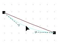
Converts a straight line segment to a curve.
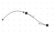
Corner
![]()
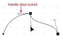
You may not notice a change when you click Corner. However, when you move one of the handles, you’ll notice the other handle stays locked, creating the cornered affect.
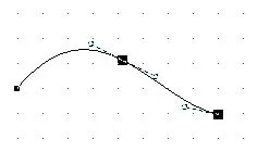
Smooth
![]()
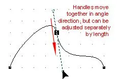
The two handles adjust with the same directional angle. Pull to change the lengths of the handles separately from each other.
Cusp
![]()
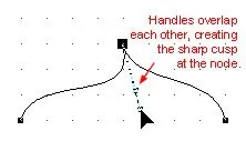
The two handles come together to create a sharp cusp at the node.
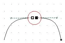
Symmetrical
![]()
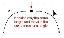
Both handles constrain to the same length and move in the same directional angle, creating symmetrical curves.


